Blink-Activated Call Bell
Empowers severely handicapped patients to call for a nurse with the blink of an eye

Use Case
Patients with locked-in syndrome, acute spine or neck injuries, or late-stage ALS currently have no way to call for a nurse in the hospital.
Designing the Glasses
Hardware:
-
Securely attached IR emitter /receiver for measuring difference in reflection from a blink
-
Designed circuit for signal amplification and filtering
-
Programmed microcontroller for calibration, signal thresholding, and text notification
Software:
-
Used MATLAB to visualize signal and implement initial thresholding and calibration testing
-
Programmed Arduino Uno in C for final, minitiaturized product


On the left is the initial photoplethysmography (PPG) set-up. It is made up of an an infrared emitter, an infrared receiver, a circuit for signal amplification and filtering, and a Digital Acquisition system to plot the signal in MATLAB.
On the right is the raw signal output. The peaks indicate blinks when the IR emitter and receiver are pointed at the eye, or across the eyelashes.

We started detecting blinks using a simple voltage threshold.
With an Arduino, we were able to threshold the blinks and activate a buzzer.
By securing the IR emitter and receiver to safety glasses, the entire device is wearable.
Prototype Development

I designed and fabricated protoboards to move the circuit from a breadboard design, to a more finalized prototype.

Verification Testing
I performed verification testing to ensure that the device algorithm could accurately differentiate between reflexive and intentional, rapid blinking.
I pe
Designing a PCB
Using Altium, I designed and ordered a PCB to consolidate the circuit component of the design. We are using solder flow techniquest to fabricate and test the boards.
.jpg)

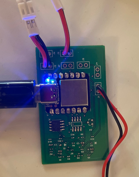
I fabricated the PCB with solder flow methods, and programmed it for full functionality.
We offered live demos of the PCB at the design expo, as an example of future product direction.
Designing an Electronics Enclosure
I designed with CAD and 3D printed an electronics enclosure for our initial prototype, topped with a laser-cut clear plate of acrylic.
.jpg)
Live Demos at Design Expo


At the end of the year design expo, we offered live demos of the product, as well as displayed an example of the output signal from the PCB