top of page
Robotics Testing
Showcasing my work on internal development projects at HEBI Robotics
160W Programmable Load
-
Four parallel BJT active sources
-
Active cooling with heat sink and 12V fan
- Programmable current source through dip switch connected to binary weighted resistor divider or direct reference voltage input
- Includes thermal shut-down with 10 degrees hysteresis
- Includes on-bard voltage and current measurement
- 48V power input, on-board buck regulators for 12V and 5V power rails

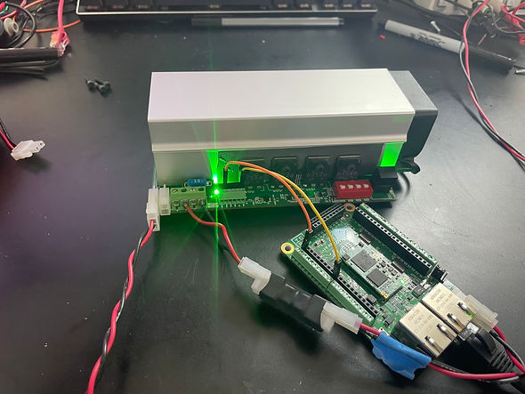
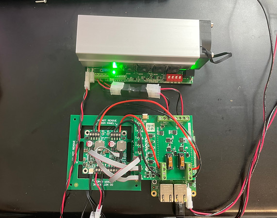
Dual DC Power Regulator Test Set-Up
-
My test board design connects to the I/Os of the power regulator board under test, as well as the programmable active load
-
I programmed the test board over ethernet with Python APIs to test the power regulators at 5, 9, 12 and 24V with a 4A load.
-
The test board includes optical relays and decoders for I/O control of the device under test, as well as on-board voltage and current monitors
-
The Python script monitors voltage and current levels as the load demand of the power regulator increases
Motor and LED Driver
-
First, I prototyped just the motor driver since the LED driving circuit had already been validated
- Motor Driver Specifications:
-
Drive 4 brushed DC motors (for air pumps) at up to 5A with bidirectional phase current sensing and limiting
-
-
Testing Results:
-
Current sensing was not high enough resolution
-
Motor speed did not have enough range
-
-
Conclusions for next iteration:
-
Select current sensor with smaller range, higher resolution
-
Select motor driver with higher frequency control
-
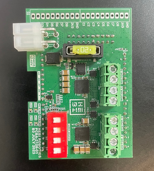

Version 2:
-
Version 2 includes 2 LED boost buck driver circuits, 2 motor drivers, one switched 5V/5A output, onboard connectors for ethernet switch and MCU module, and four SPI channels
bottom of page